2020 Kia E-Niro VESS/Reverse Chime defeat solution

  • Thread starter Thread starter ENirogus
  • Start date Start date
  • Replies Replies 193
  • Views Views 124K
Thanks to
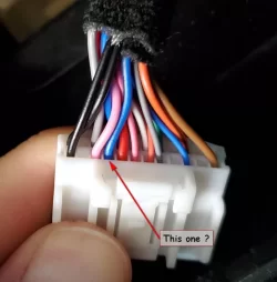
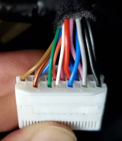
OK...so let me make sure I have the wiring right then....Kia wiring harness on the left, switch wiring on the right below

KIA PINK to RED switch wire
KIA BLACK to BLACK switch wire
KIA blue/black to BLUE switch wire

Now where does the GREEN switch wire go to on the KIA harness?
And the YELLOW switch wire goes to nothing.

Much appreciated!! This is going to be huge.

The green[common] is also ground so it get connected also to Kia black, or just jumped on the switch

Thanks to all who contributed to this thread. I just picked up a 2022 EX Premium last week and I'm already having stress dreams about backing up from my driveway in the middle of the night. I just wanted to confirm a few things before I tackle this project.

Will these parts on Amazon for the T-Tap disconnects and terminals work?
https://www.amazon.com/gp/product/B08R666X5Y/ref=ox_sc_act_title_1?smid=A1NW4ONHSII4F0&psc=1

I
was thinking of this switch Cory referenced: https://www.amazon.com/gp/product/B07GTJBR59/ref=ox_sc_act_title_2?smid=A1POY47GM797OI&th=1

In terms of process, is this the correct order:
  1. Snap on disconnects to Blue, Black and Blue wires
  2. Connect terminals to disconnects
  3. Insert switch wires to corresponding terminals
  4. For the green ground wire what do I need to close it or do I connect to Black terminal too?
Am I missing anything? Thanks again for all the help!
 
Turns out I actually got the 12mm one


Sent from my Pixel 3a XL using Tapatalk

Thanks as I wasn't even thinking about the size.

Is this the correct order and all I need to do?
  1. Snap on disconnects to Blue, Black and Pink wires
  2. Connect terminals to disconnects
  3. Insert switch wires to corresponding terminals
 
When the car is off there is no power to any of the wires, so the order of connection is not very important. Your process should be fine
 
Now you need to add a momentary switch across these two points. Those red plugs will accept a 1/4 MALE quick disconnect, not the more common female

https://www.mcmaster.com/7243K118/

You can wire it differently, this is how I chose to do it. View attachment 12207

Hey Guys, just got my brand new Niro EV "MY 22 Germany" 2 days ago and can't stand the VESS. On the model I tried at the dealer prior ordering one there was a switch to shut off VESS. Now aperently all MY22 don't have it anymore.
So I just ripped the switchboard apart and took some photos.
Is this the right PIN?
Mine is Blue-White.
 

Attachments

  • connector_front.webp
    connector_front.webp
    35.3 KB · Views: 145
  • connector_back.webp
    connector_back.webp
    32.4 KB · Views: 134
  • Switchboard_back_MY22_GERMANY.webp
    Switchboard_back_MY22_GERMANY.webp
    54.3 KB · Views: 136
  • Switchboard_front_MY22_GERMANY.webp
    Switchboard_front_MY22_GERMANY.webp
    47.1 KB · Views: 124
Someone has priced out the switch panel, it wasn't cheap. Also you need an appropriate VIN to order the part
I think I am going to order a spare fuse panel so I can drill a hole in it guilt free
 
I went to my dealer today for the panel.
He used the VIN from last year niros.
He can order it for 161€.
But there is no delivery date for this item.
I'm gonna make a choice tomorrow.
If I'm gonna get it I will let you know if it works..
 
  • Like
Reactions: 3XG
Just wanted to say thanks for this. That noise has been driving me nuts. Some extra thoughts since I just completed this:
  • I loosened both screws (there are 2) on the lower panel. Then pull the top of the lower panel out just a little bit. That will release the switch trim panel that contains the switches. Also lower the steering wheel as far as possible - it makes it easier to reach behind the switch trim panel to pull it out.
  • Disconnect the wire harness from the lower trim panel (with the charge button) - that will make it easier to get more of the wire out to work on it.
  • I used 3M scotchlok for tapping. They're a bit harder to use since both wires have to be in place when you compress them. But I don't trust the random no-name brands of the other type.
  • I used an old 3 pin fan cable extension from a computer I had laying around to make a connector. Cut it in half and wired one end to the switch and one end to the taps. That way if someone needs to pull the trim panel, they can disconnect it easily.
  • Locating the hole would be simpler if you also pull the lower trim panel - I'd have preferred it to be centered on the switch cluster but with the airbag in that panel I didn't want to mess with it and there are plastic mounts behind the panel so you have to be careful where you drill.
  • I only had a 1/2" bit (would have preferred a 15/32) and it stressed the plastic on the edge of the hole a little bit and turned it white. Used a black sharpie to color those in before mounting the switch and no one will ever notice.
    Sc4dt2C1fvGQ1mdx9
    View media item 549
 
That did it, thank you!! I'd wired Ground to one of the NO terminals instead of the minus. Now I have a working kill switch; the LED is lit when VESS is on, and dark when VESS is off. Perfect!

I'm sure my neighbors are all grateful to you since they no longer have to hear me when I get home from work late at night. Woot!

I bought the same switch (and one of the larger ones mentioned in a later post) and now am trying to merge @pepsi216 and @ENirogus comments on how to wire this up. I think understand what ENirogus is stating but that differs a little from the above (as I think one of the NO terminals is also connected to Ground).

I believe the attached image and the below is the correct way. This appears to make sense (to someone who took EE 30 years ago). When the button is pressed, the normally open (NO) circuit is closed and momentary provides a path from ground to the VSS Switch (just like the KIA schematic). Switch-Opposite.webp

Kia Switch
Blue/Black[VSS Switch](pin 9) ->Blue(1 of 2)[Normal Open(NO) Pin]
Black[ground](pin 24)----------->Blue(2 of 2)[Normal Open(NO) Pin] and Black[Negative of LED Switch]
Pink[VESS Indicator](pine10)--->Red[Positive of LED Switch]


Any comments before I do this in the coming days?

Thanks
 
Blue/Black[VSS Switch](pin 9) ->Blue(1 of 2)[Normal Open(NO) Pin]
Black[ground](pin 24)----------->Blue(2 of 2)[Normal Open(NO) Pin] and Black[Negative of LED Switch]
Pink[VESS Indicator](pine10)--->Red[Positive of LED Switch]

Yes, that looks right, assuming the two NO pins are shorted (connected) momentarily when the button is pushed (not totally spelled out by the data sheet, but seems to make sense). I just did it recently and it went better than expected. Let us know how it went with you!
 
With the basic solution here (which I am still considering doing) I believe I would normally press that button right after almost every time I start my car, especially at my house. One advantage of the simple unplug solution is I don't have to that. Wish button worked in opposite manner...press to enable VESS.

(Note I tried to unplug cable from narrow gap in hood but couldn't unlock the damn connector. Not sure where exactly this unlocking tab is located. Will try again...any tips appreciated!)
 
I bought the same switch (and one of the larger ones mentioned in a later post) and now am trying to merge @pepsi216 and @ENirogus comments on how to wire this up. I think understand what ENirogus is stating but that differs a little from the above (as I think one of the NO terminals is also connected to Ground).

I believe the attached image and the below is the correct way. This appears to make sense (to someone who took EE 30 years ago). When the button is pressed, the normally open (NO) circuit is closed and momentary provides a path from ground to the VSS Switch (just like the KIA schematic). View attachment 13904

Kia Switch
Blue/Black[VSS Switch](pin 9) ->Blue(1 of 2)[Normal Open(NO) Pin]
Black[ground](pin 24)----------->Blue(2 of 2)[Normal Open(NO) Pin] and Black[Negative of LED Switch]
Pink[VESS Indicator](pine10)--->Red[Positive of LED Switch]


Any comments before I do this in the coming days?

Thanks
Ok. Did this. Not exactly the results I was expecting meaning:
1) Expected: pressing button disables VESS
2) Expected: pressing button again re-enables VESS
3) Not expected: Switch LED does not stay on when VESS is disabled
4) Not expected: Switch LED only lights for the time the button is actually pressed in

With that behavior, I relooked at the Apiele data sheet. I assumed that configuration 1's (the photo that I had above) statement of "Press the button, led light on" meant stayed on, but no that just means it momentarily lights when pressed in like I observed.

I need to look at the post about how the bigger Apiele switch was done as that behaviour is what I wanted. I have one of those switches also, so I might do a swap. Will see.
 
Job done. Moved over to the bigger switch which as wired will be lite up when VESS is enabled. I decided to drill into the fuse box cover due to 1) if I screwed up the drilling, easier to replace and 2) in case of warranty/dealer maintenance, I might want to hide the switch. Another advantage to that larger switch is that it has a disconnect at the back.


Final VESS Defeat Switch.webp
 
Ok. Did this. Not exactly the results I was expecting meaning:
1) Expected: pressing button disables VESS
2) Expected: pressing button again re-enables VESS
3) Not expected: Switch LED does not stay on when VESS is disabled
4) Not expected: Switch LED only lights for the time the button is actually pressed in

So, it sounds like the NO pins shorted momentarily as they enabled/disabled VESS correctly.

But there must have been a connection inside the switch that controlled the LED, as it wasn't controlled by the +12V on the pink wire? Maybe it wouldn't have lit if the +12V on the pink wire wasn't there? If so, that is unexpected, given what was shown on the data sheet. Glad you had the other switch!

BTW, I put my button in exact same place as you did, on the fuse door, for the same reasons. Don't think I have seen that done before, but I thought it made sense as well.
 
I think I am going to order the fuse box cover as I like the placement and it should be cheap
I think there is a way to [mis] wire the switch that it will act as noted, above, but it sounds like they have resolved it
 
Back
Top