Thanks 3XG for that excellent walkthrough! Are these the taps you used? https://www.amazon.com/gp/product/B001MPW54G
As an Amazon Associate we earn from qualifying purchases.
Thanks 3XG for that excellent walkthrough! Are these the taps you used? https://www.amazon.com/gp/product/B001MPW54G
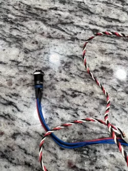
Pleasee post pics of this as i really need this done on mine asap. Thanks in advance!I did mine this morning! I used the same switch that some others are using: https://www.amazon.com/dp/B07GTJBR59
I decided I didn't want the LED to light up, so my wiring is super simple:
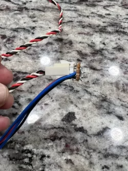
1. Blue wire on the switch goes to the blue-black wire on the car.
2. Green wire on the switch goes to ground. Similar to others on this forum, I grounded it to one of the bolts behind the dashboard that goes to the frame.
And that's it! Just one wire tap on the car. And I only used 2 of the 5 wires on the momentary switch.
Too small of a one can cut strands, and unfortunately you don't know unless you pull it apart and inspect.
With great gratitude to this thread, I can now turn off the VESS at will. Freedom from din!
To make things easier to explain, I compiled 3XG's step-by-step into a PDF document, attached here for anyone's use.
@Greg Elmassian: Did you ever get to try your capacitive switch idea? I had the same idea and found your post earlier in this thread.
Also saw this reddit thread with some guys who installed a switch into the VESS blank in the panel https://www.reddit.com/r/KiaNiroEV/comments/ot0e7e/vess_defeat_switch_solution/
I'm dreaming of a hybrid where a capacitive switch is installed in the VESS blank for a potentially full incognito install. In the photos in the reddit thread there might even be a place to solder the switch connections without having to tap into any wires.
I haven't worked much with capacitive switches. Would the touch sensitivity be local enough? or would touching part of the switch cluster cause it to change modes? Any comments appreciated.
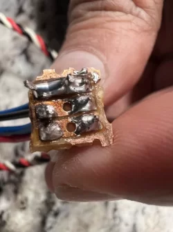
Another alternative might be to 3D print a functioning switch insert and solder onto the circuit board the appropriate missing elements . Looks like a momentary surface mount button, a resistor and an LED may be all that is needed. Might take some research to determine the proper switch make and model.
@Greg Elmassian: Did you ever get to try your capacitive switch idea? I had the same idea and found your post earlier in this thread.
Also saw this reddit thread with some guys who installed a switch into the VESS blank in the panel https://www.reddit.com/r/KiaNiroEV/comments/ot0e7e/vess_defeat_switch_solution/
I'm dreaming of a hybrid where a capacitive switch is installed in the VESS blank for a potentially full incognito install. In the photos in the reddit thread there might even be a place to solder the switch connections without having to tap into any wires.
I haven't worked much with capacitive switches. Would the touch sensitivity be local enough? or would touching part of the switch cluster cause it to change modes? Any comments appreciated.
Another alternative might be to 3D print a functioning switch insert and solder onto the circuit board the appropriate missing elements . Looks like a momentary surface mount button, a resistor and an LED may be all that is needed. Might take some research to determine the proper switch make and model.
Continued from previous post...
7. Wrapping It Up
At this point all connections have been made. Next, I figured I would add a little bit of insurance in case something wiggled loose, by adding a couple of layers of electrical tape… once around each wire tap (7A) and again around both of them (7B). Then, to add a little strain relief, I used 2 small zip ties (see yellow circle in 7C) to secure the new wires to the existing wire loom. 7D shows the two new power wires and the ground emerging from the fuse panel opening. 7E shows how much wire I left “just in case” of… I’m not sure what, but since I had the wire, why not?
8. Finished Product
And that is it! All that is left is to neatly wind up the wire, stuff it in, and replace the fuse panel (8A) and see if it worked, which it did! So, every time the Niro EV is started, the LED in the switch turns on to indicate that the VESS is active (8C). Press it once to turn off both the VESS sound and the LED in the switch (8B). Originally, I thought I would be turning it off all of the time, but as it turns out, I usually leave it active in public parking lots, just in case someone is back there and helps me avoid an accident. I apparently don’t mind irritating complete strangers and, who knows, it has the potential to save a life. But… around my house, I pretty much always turn the sound off when backing either out of or into my driveway. Then, when I need to go forward, I always turn it back on, because I love the spaceship sound. It’s nice to have the option.
So hopefully that took a little more mystery out of connecting the dreaded “VESS Disable Switch”! Again, thanks to those that took the time and effort to document this in the past! I have newfound respect for you!